Xiaomi Mijia M365 Grip Buttons, Blinkers, and Horn
 |
 |
Make your scooter speak car.
My first pass at a turn signal mod was pretty rudimentary but it did inspire a new interface alltogether. The back blinkers aren't quite obvious when looking from the behind and pretty much unreadable from the front. The buttons to the side of the grips weren't easy to press and added weight to the handlebars, something I didn't anticipate.
It was ridiculous trying to cram an Arduino Uno in there. Smaller boards make a lot more sense with such a tight formfactor such as a Particle Photon, which allows modifying the firmware via WiFi.
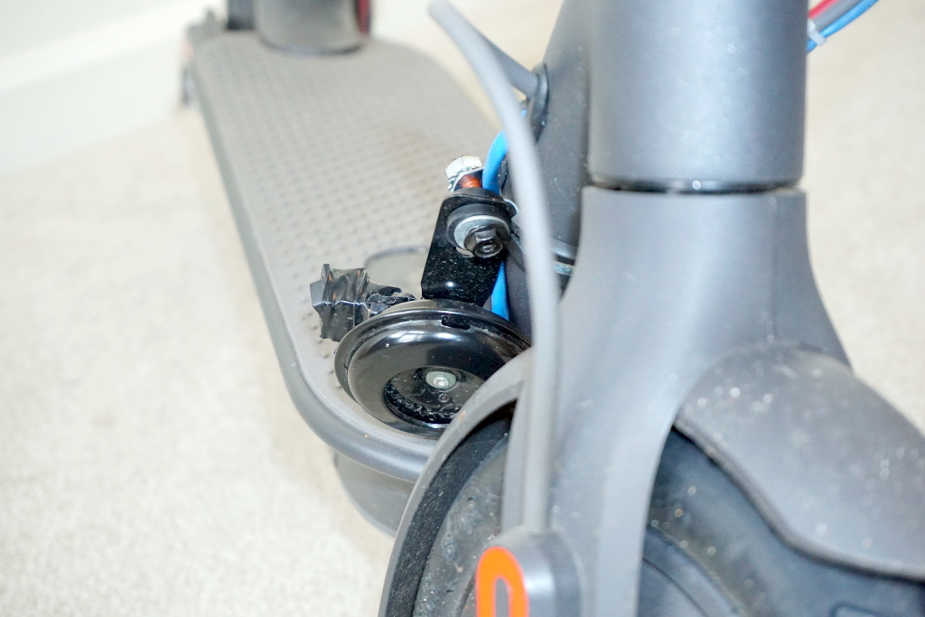
I've also ridden the scooter enough to bump into one too many dangerous traffic situations, so installing a small motorcycle horn was also a priority.
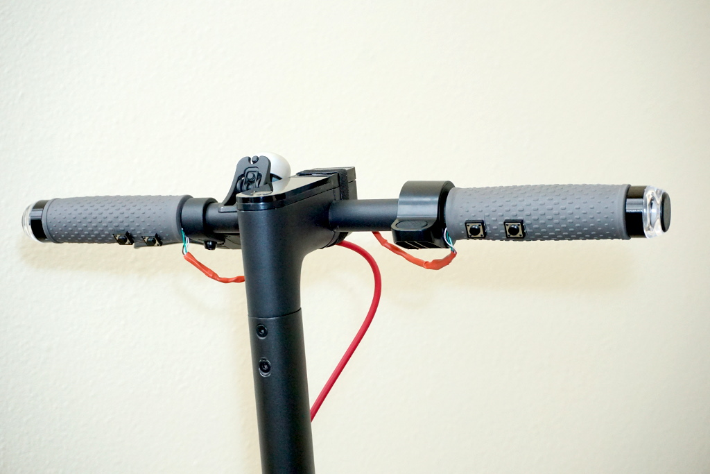
I hacked on the grips to put blinkers on their edges and to install four buttons under where your fingers would naturally rest. Index fingers toggle blinkers, middle fingers control a quiet and loud version of the horn. I sourced 12V from the scooter's battery and designed a place for a Particle Photon or Arduino to live that makes efficient use of footboard space.
Here's the breakdown of my mod, version two.
Switch design
Initially I hunted down a sturdy two-button handlebar module, but I found it unexpectedly awkward in practice. The button closest to the grip worked well; the other not at all, despite sitting only about an inch farther away. I debated many mounting options, ranging from drilling holes in the rubber for a 6 x 6 x 15mm tactile button to poke out of, to cutting away some of the rubber to make room for a fully metal handlebar-mounted motorcycle pushbutton facing down, to sliding a small PCB-mounted version into the forward-facing handlebar recession that you'd push through the rubber. None of those options felt quite good enough.
Eyeing possibilities after ordering a tactile switch assortment prompted me to scrap the whole idea in favor of mounting them on the grips, directly under the fingertips. I went with DIP 12 x 12 x 5mm tactile switches mounted directly under each index and middle finger. A month of testing proved this a vastly better interface than a separate switch module.
 |
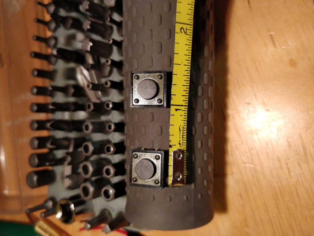 |
Note the angle. 90° from the front, directly down, makes them too easy to bump. 180°, directly behind, makes them too hard to get to. 45° turned out just right-- or at least so far. An inch apart is optimized for use with fingers in gloves. Without gloves, that provides space between for fingers to rest.
 |
 |
In the end, for each button I decided to cut one side's leads off and slide it into a small cut in the original rubber grip. This (1) provided a channel to run the wires, (2) as a result secured half/most of the switch, (3) sealed the soldered connections, and (4) allowed sliding the component front-to-back to adjust the position .
I am now applying small dabs of super glue to the other side to fully secure each one, now that I like the positioning. To be honest this isn't mandatory as the leads hold them well.
 |
 |
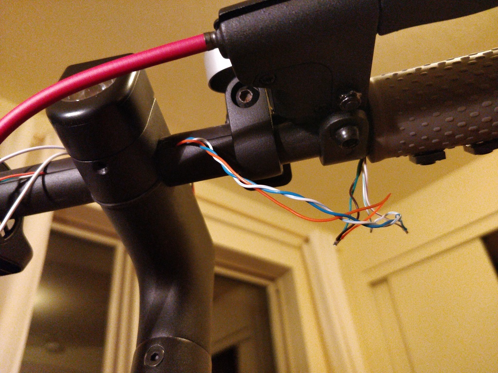
Individual strands of ethernet cabling worked really well for these logic-level lines. They're thin and fairly rugged, tucking nicely within the grip. I them outside and around each built-in control. However, you could just as easily bury them. In hindsight, I should have ran them inside the back of the bar. However, it looks decent with some heat shrink tubing.
 |
 |
Grip Blinkers
Blinkers on the edges of the grips are a necessity. I cycled through the options including 3D-printed adapters that fit into the crescent-shaped cavity in the handlebars as well as specialty grips with blinkers built-in. These were intriguing; however, I couldn't get a good answer on the overall weight of these models and the amperage of the lights. Plus, of course, that would change the plan for mounting tactile switches.
 |
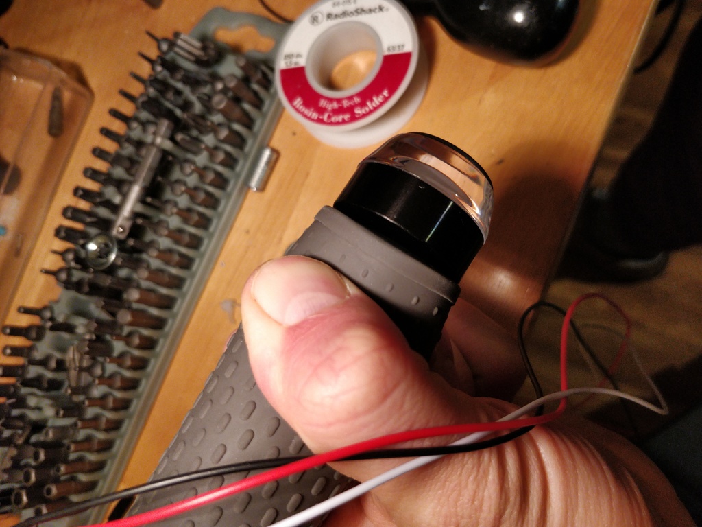 |
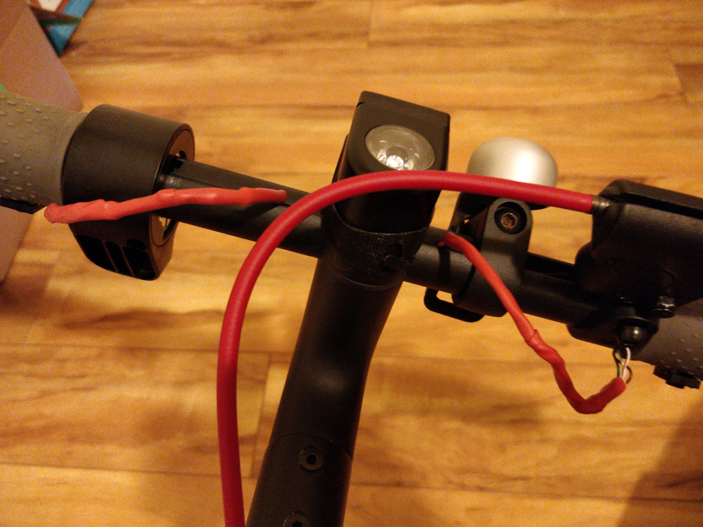
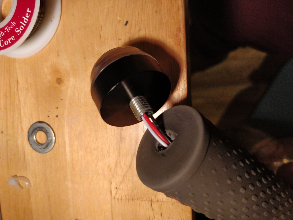
I went with the hacky way of mounting the lights directly to the rubber ends of the grips. While I would have preferred mounting to metal or at least plastic, this much easier approach turned out to be good enough.
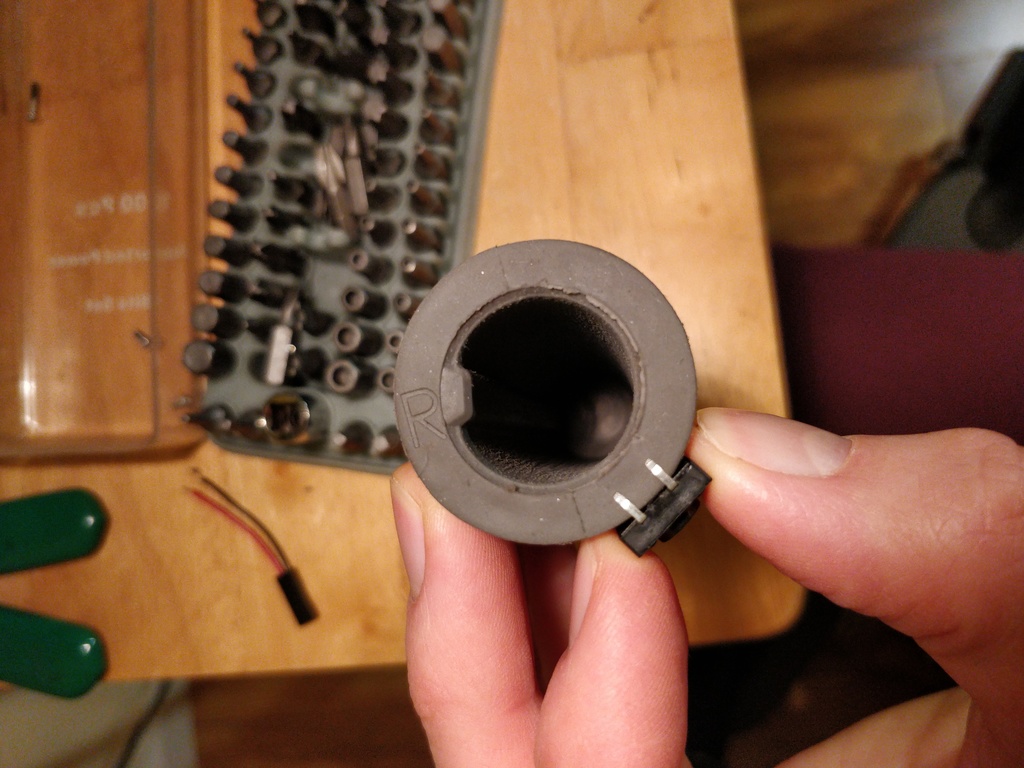
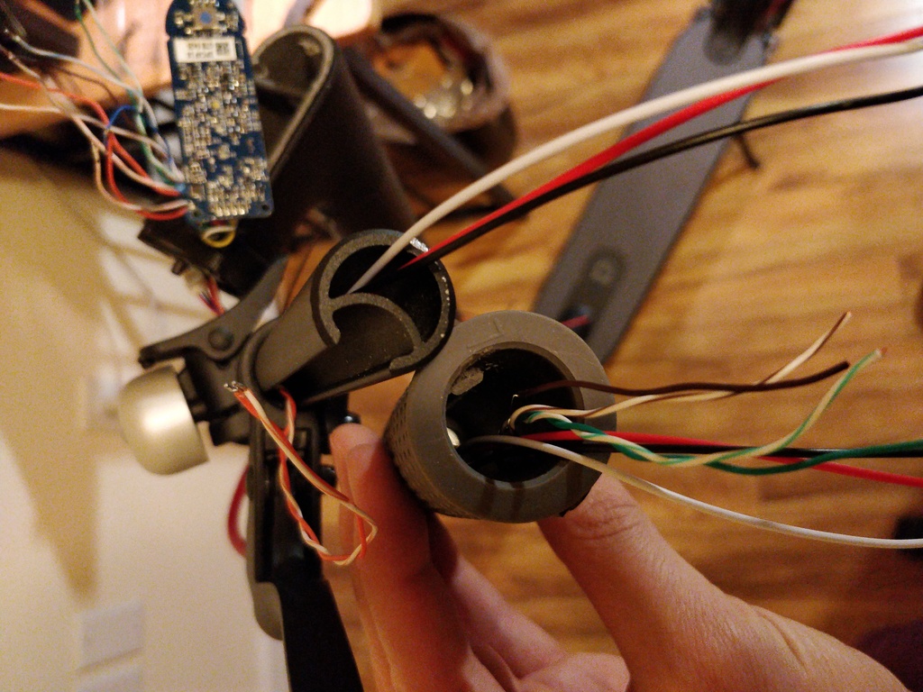
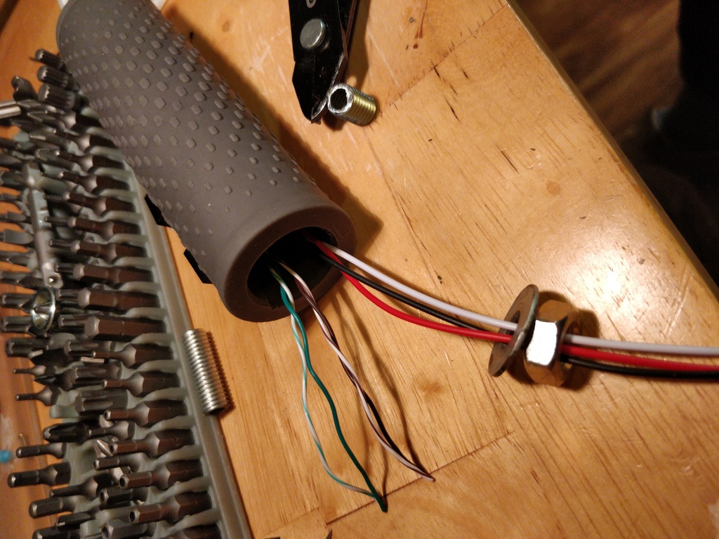
As with those mounted in the footboard, I cut the hollow bolt down to about 3/4", drilled a centered hole, slid the bolt along the wiring, and gently tightened while grabbing the whole rubber end. Sounds janky, but wasn't bad at all.
I ran the blinker wiring through the back cavity of the handlebars. While pulling them it's easiest to have the BLE area disassembled and the handlebars loosened and somewhat dangling.
 |
 |
And now a word of warning. The cheap knobby-looking blinkers I found on Amazon from my first attempt are the perfect formfactor and look. However, the ones I received have defective LEDs. Two of the four are starting to flicker and dim. I observe several sellers of identical models on there which usually indicates a copied model produced by several parties. So no guarantees on QA.
Perhaps there's another similar model that won't die, just takes some more hunting.
Since the lights have an amber and a white mode, I have rewired the failing one in the back to the white option for now so it at least works.
The Brains
You may have chuckled at my earlier solution where I crammed everything above the driver board rats-nest style. Well, I eventually fried that Arduino Uno. Clearly, that was a learning experience and as a result inspired a new design.
I picked up an Arduino Nano and a Particle Photon and learned there are pros and cons to each. The big advantage of the Photon is it can take firmware updates over WiFi, avoiding disassembly whenever you want to make a tweak.
The Arduino's logic level voltage is 5 volts, which is required to work with MOSFETs, whereas the Photon uses 3.3V. This necessitates a logic-level converter sitting between it and the MOSFETs, which is effectively another set of mini MOSFETs that convert 3.3V to 5V. The big drawback to this approach is that there is 5V going into your MOSFETs briefly when you turn the scooter on, before the Photon has a chance to say "no, set those pins low." That causes all lights to briefly turn on and yes, the horn to blast too. I just keep the safety switch turned off when not using the scooter. I'm sure there's a good workaround for this; however, the logic-level converter is already pushing it. Easier to just use a board that works with 5V.
 |
 |
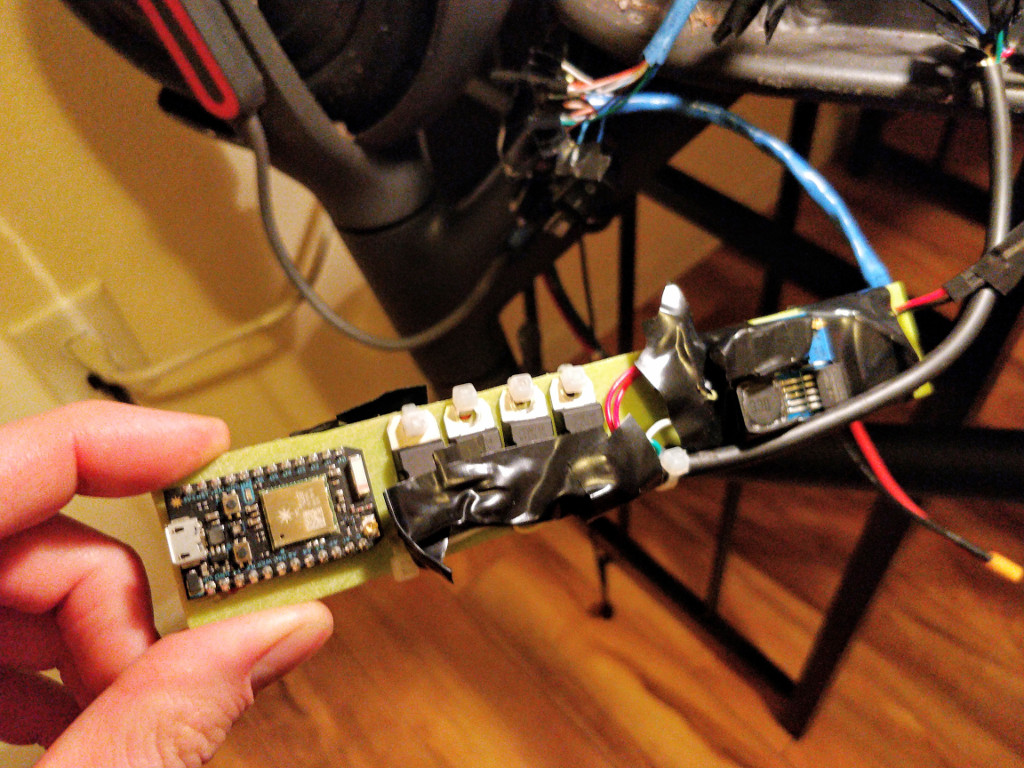
The other caveat to the Photon is that by design it will attempt to connect to WiFi before running your program. I put the board into "manual mode," which leaves it up to the programmer to decide when it does so, and chose a grip button to hold down on boot-up to enter this mode. That means you have to hold it to hit it with a new program. See the early return in my .ino.
Aliexpress and Amazon are bursting at the seams with Chinese Arduino replicas. One greatly underrated improvement of these replicas is that they use a different chip and USB socket which greatly reduce their formfactor. Instead of a bulky rectangular PC chip, it uses the much flatter and tinier CH340. Instead of the old standard USB plug which is like 3/4" wide and deep, it uses microUSB. I also recommend choosing one with unsoldered pins, allowing for proper through-board soldering rather than against a pin.
Here's what I went with:
I am planning to work on the firmware for awhile with the Photon, and eventually flip to an Arduino once it's polished enough.
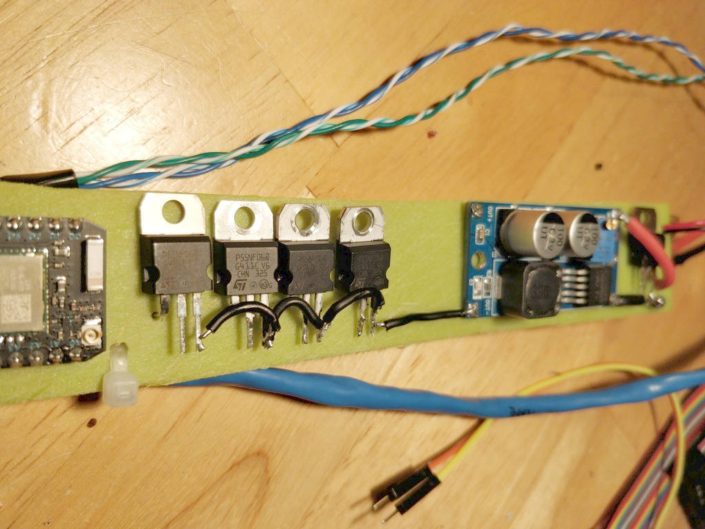
Design of slip
I mounted everything on a "slip" which just a piece of plastic I repurposed from an Ikea cutting board. I made it long and skinny to fit in the scooter's connector piece.

The slip provides these components a place to mount:
- The Arduino or Photon
- 4x MOSFETs for controlling 12V components from the microcontroller's 5V logic level
- The 5V-60V to 1.25V-30V step-down voltage regulator
- 1x MOSFET for toggling the whole thing on/off gated by the scooter's 5V
If using a Photon:
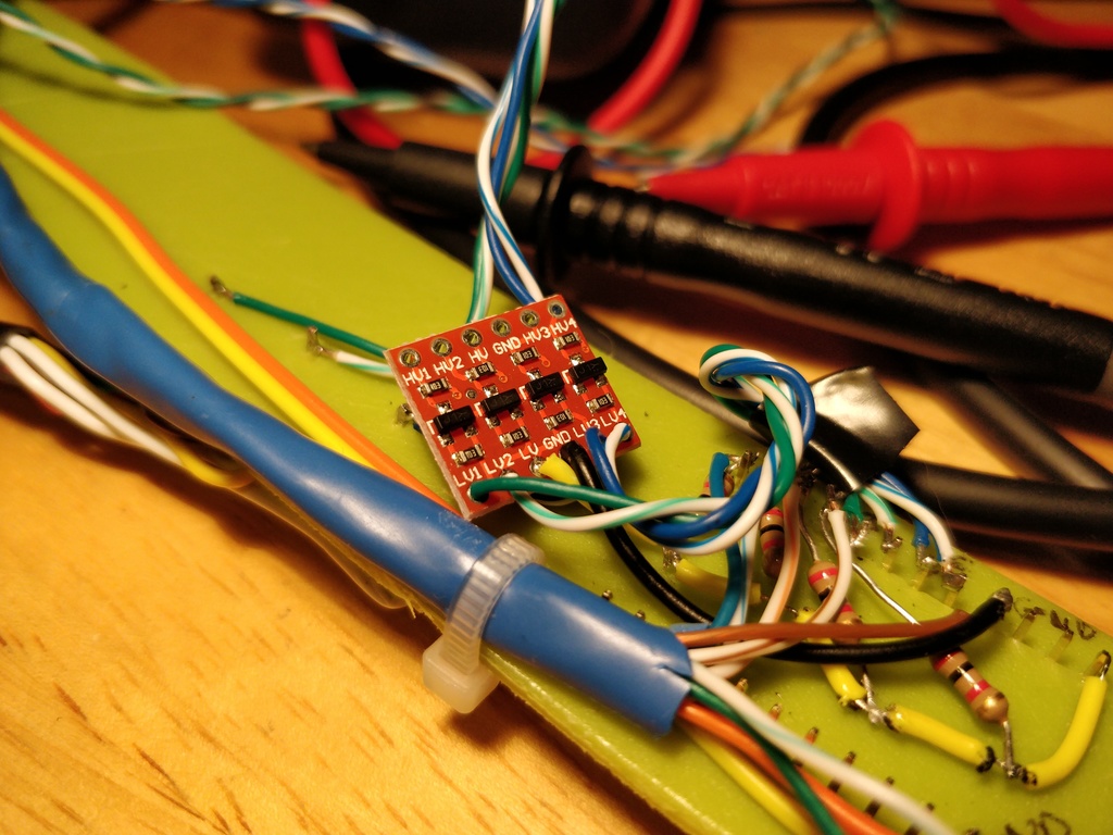
- The 3.3-5V logic level converter (see schematic)
- A 12V-5V step-down voltage regulator (see Cross-Talk Issue)
The general goal was to put 12V stuff on one side and 5V stuff on the other. The gate terminal of each MOSFET I bent and put through to the 5V side. I also made sure the assembled slip was as flat as possible so that it fit. I found that 1" wide by 7 3/8" was a pretty ideal size.
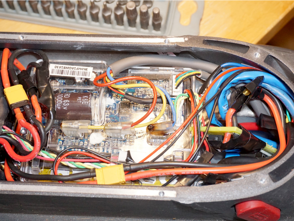
Cabling is bulkier than you might think. The microcontroller and the rest of the components slide up and out of the way into the connector piece, making room for the wiring and connections above the driver board.
The assembly isn't completely buried in the connector cavity. It sticks into the top of the footboard by about an inch. No reason it can't be shorter, though. It would just make the component spacing tighter. The key is to make sure there's still clearance for the bottom cover.
 |
 |
Components, power draw, and the fuse

Here's schematic. Usual disclaimer, I am not an electrical engineer, this is a best attempt. Also, the MOSFET symbols are wrong.
Note the coloring of some of the connections corresponds with ethernet strand coloring.
The mod adds a horn, four blinker modules, and extra slot for a future option. Putting this all together required understanding that MOSFETs come in two overarching flavors, P-channel and N-channel. I wasn't able to get the P-channel type switching my components properly—much more to learn before I get there.
N-channel MOSFETs work on the negative side of the component, so the positive side is common. The four MOSFETs on the slip are all wired to the negative side of each component.
Anything logic-level I connected via ethernet cabling or otherwise a scrap 7-pin cable for higher-amp needs. I soldered all wired connections rather than using plugs, with the exception of the XT-30 Y cable. I would spend more time here if I had to do it again as it would be nice to more easily disconnect everything. Perhaps these multi-pin wires & connectors would work well.
The step-down regulator driving everything handles up to 3A. So the breakdown is:
- 250mA per blinker, x4 = 1A
- 1.5 A for horn
- Circuitry about 35mA when tested, definitely under 50mA
The total comes to about 2.5 A, supported easily by the regulator with 500mA to spare on a future addition.
 |
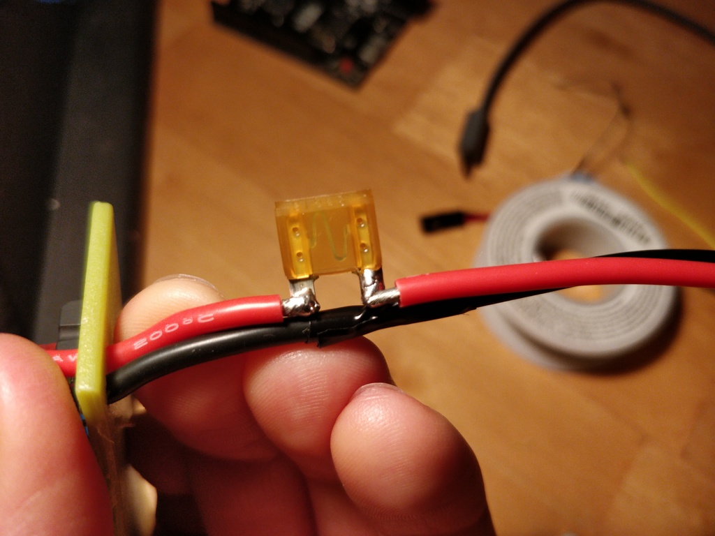 |
I chose a 5A automotive fuse, to cover the maximum load plus some wiggle room. Initially I picked up a fuse holder, but the thing was ridiculously bulky when installed. Soldering directly to the fuse's leads saves a lot of space, but does require a tiny bit more work if it blows. In prime hacking style, I wrapped the leads with electrical tape.
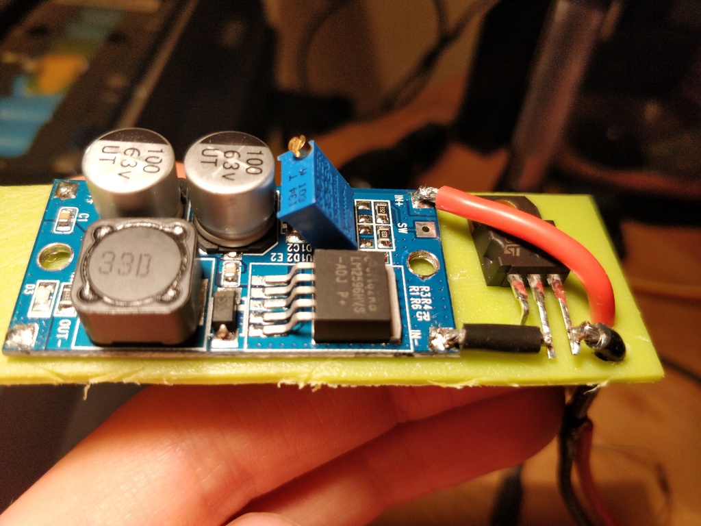
Crosstalk Issue
Initially I tapped into the scooter's 5V thinking I could easily run the logic-level components directly off of it. That way, it already switches with the scooter. Lots of painful trial-and-error revealed that getting "too close" to this 5V source results in a crosstalk issue where manipulating the scooter's controls causes weird behavior in anything controlled by the Arudino or Photon. For example, throttling up caused the blinkers to gradually turn on.
Unconcerned about showing my ignorance about electronics, I'll say my best understanding is that is caused by inducted voltage from the existing circuitry. But I think it best to defer to someone else to explain this well. For our purposes, the lesson is to source your own 5V off of your main step-down regulator. I used an additional second step-down board to go from 12V to 5V:
https://www.amazon.com/gp/product/B016VG8XI2
I also hooked up 2K pullup resistors thinking that the microcontroller's built-in ones were too weak. Admittedly I don't know for sure if that made a difference. My hunch is that sourcing my own 5V made the difference.
Video Demo
Here's a quick video demo of it in action.