Xiaomi Mijia M365 Arduino Turn Signals
If you haven't already noticed, I'm pretty seriously excited about e-scooters, in particular the Xiaomi M365. One thing it could really use, however, is turn signals. It's not really safe to take your hands off the handlebars while turning, so I got inspired to do a hack project to integrate some signals into the scooter. This means tapping into the existing battery and making sure all add-ons fit in the footboard.
I put this together with an Arduino, a handlebar-mounted set of buttons, and four LED knob-looking round lights attached to the scooter's footboard.
NOTE I've since written a more updated and improved version of this post.
Key Items
- LED Handlebar Turn Signals
- Arduino UNO ATmega328P Board
- 5V-60V to 1.25V-30V @ 3A Adjustable Voltage Regulator
- STP55NF06 MOSFETs
- XT30 Male & Female Pigtails
- 7/8inch Type D Keenso Handlebar Momentary Buttons
- Small Piezo Buzzer (dime a dozen)
Design of interface
Single push left or right button toggles the respective blinker on/off.
The foremost need is the ability to toggle the left or right signals. This means some type horizontal control. At first I built a prototype with this button set, but I deemed it too flimsy and very much not water resistant, which is a hard requirement for me.
After more research, I decided two momentary horizontal buttons could actually be a better interface anyway, leading me to this unit. As a bonus it has indicator lights. It's somewhat heavy, however, so I may reapproach this later.
Hold either button to cycle through background mode.
The 'background' mode, active when not actually signaling, has a running lights setting, possibly with a slow blink, for visibility/safety. I bound the left button to that option and the right button to steady auxiliary lights.
Hold both left and right buttons to toggle hazards.
More of a gimmick but if you're stopped and can push both buttons at once, I implemented hazards.
Separate button for the horn
After scooting for awhile, I've learned a horn is an absolute necessity. I cannot easily count the amount of times a car has almost turned into me. Mounting the horn itself is a separate challenge, as I wanted everything to integrate as tightly as possible into the stock scooter body. But I'm keeping it in mind for the future.
Arduino Implementation
The program that reflects this lives in this repo:
mcnelson/xiaomi-m365-arduino-turn-signals
I implemented this using PlatformIO.
Run
platformio runto compilesrc/main.ino.Plug in your Arduino and run
platformio run -t uploadto compile & upload.Run
platformio device monitorto see any debug output such as:Serial.println("Started.");
'Schematic'
Here's an attempt at a schematic/wiring diagram. Warning, I am not an electrical engineer.

The power source
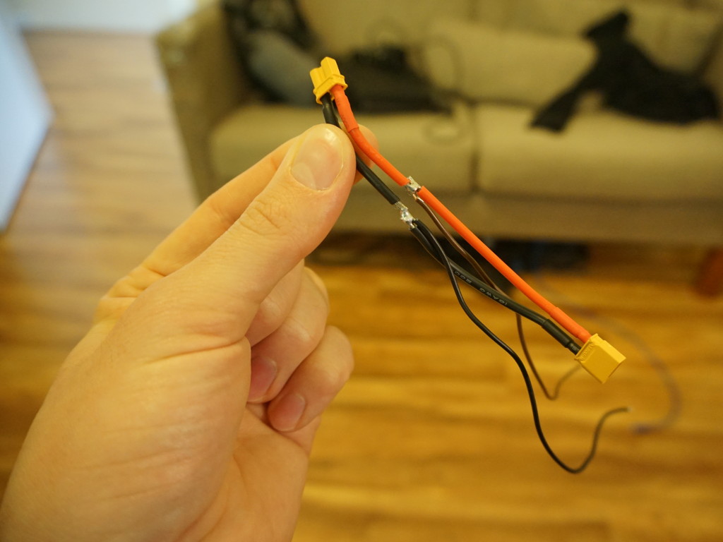
I used the XT30 pigtails to make a sort of Y-cable to drive the Arduino and the lights. This avoids having to install a second battery.
The voltage coming out of the battery ranges from 30-42V. I ran the output from the spliced cable into the DC-DC converter and adjusted its output to 12V via the potentiometer. While it would be convenient to run the arduino off of the Scooter's 5V supply, I found that the board required a 12V supply to output enough voltage, 4.5V, to properly switch the turn signals via the MOSFETs. The drawback to this is the board is still running even when the scooter is off, but I plan to read the scooter's +5V pin with the Arduino and put it to sleep when not receiving a signal.
Tapping into the scooter's 5V
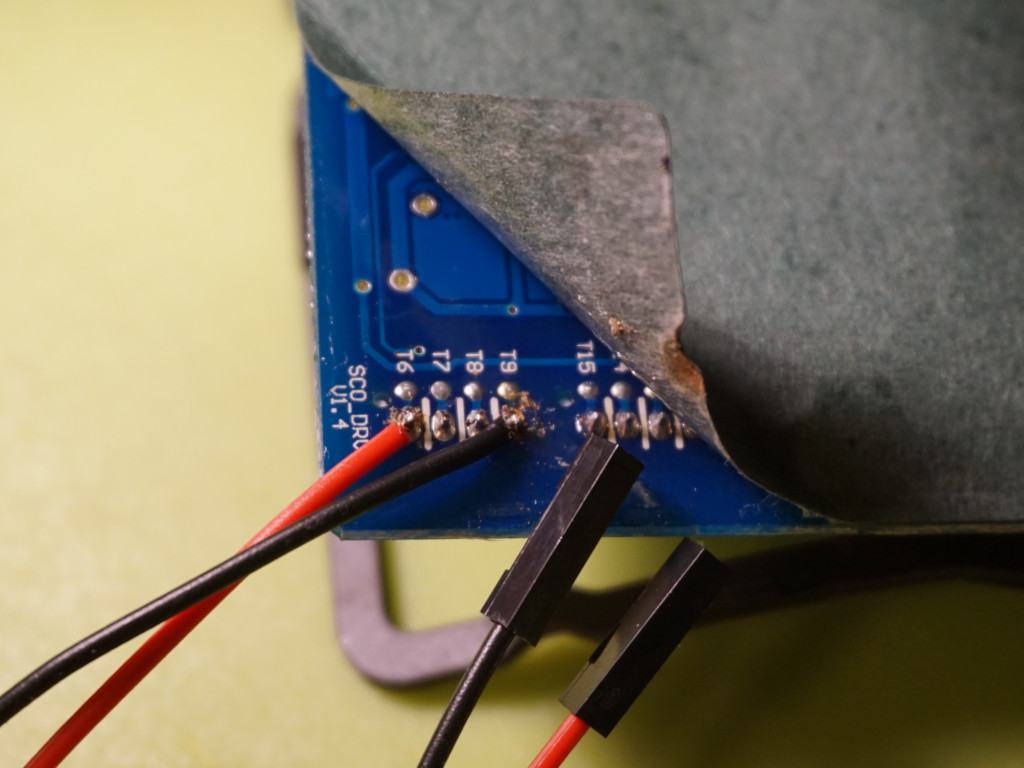
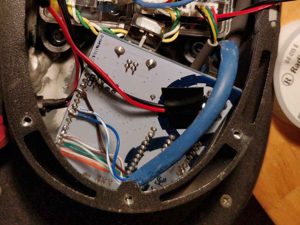
The 4-pin B04B-PASK socket closest to the edge of the driver board is where the bluetooth module plugs in (BLE). The outermost pins on it are +5V (T6) and ground (T9). As I wasn't able to find this particular connection online to make a Y-cable, I decided the next best thing would be to solder a pigtail into it from the bottom.
I unplugged everything from the driver board and pulled it out. It's pretty obvious where things plug in. Still, had to be very careful because the bottom of the board's metal casing is layered in thermal paste for good heat dissipation on the frame.
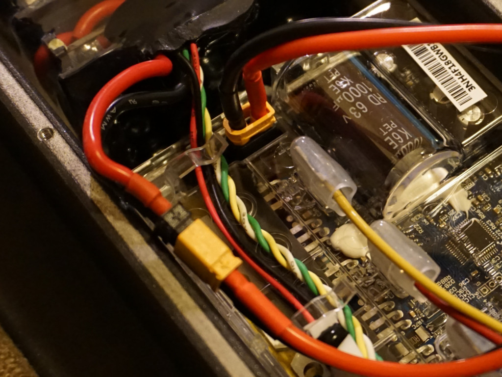
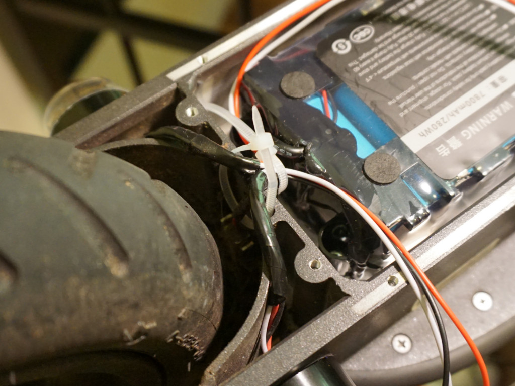
The Arduino in the Footboard
I used a small square of a disused Ikea cutting board to mount the FET switches and DC converter. The primary reason for its skinny design is to fit it in the connector piece that joins the footboard with the stem.
Turns out, wires take up more room than they look! There is only barely enough room to put it in there. Like I said, my priority with this project was seamless integration, so that's all fine with me.
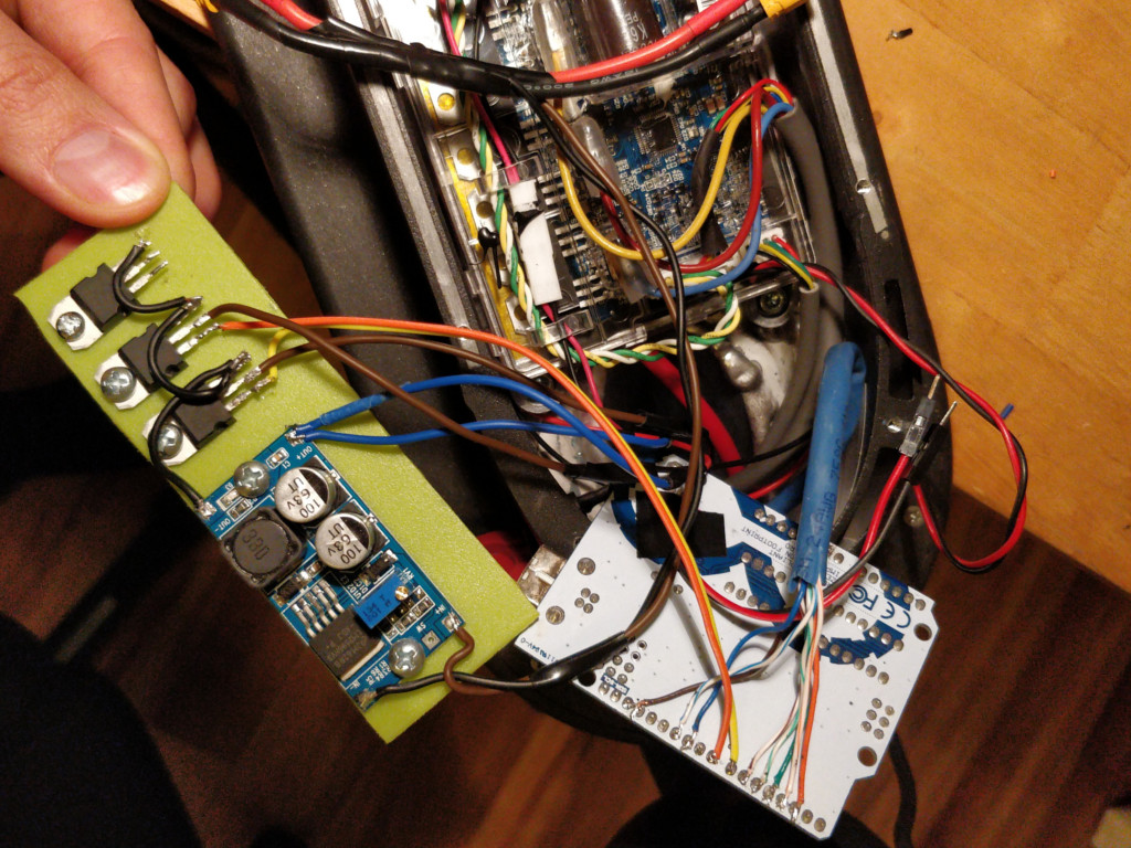
The arduino board barely fits above the driver board, in the space by the charging port.
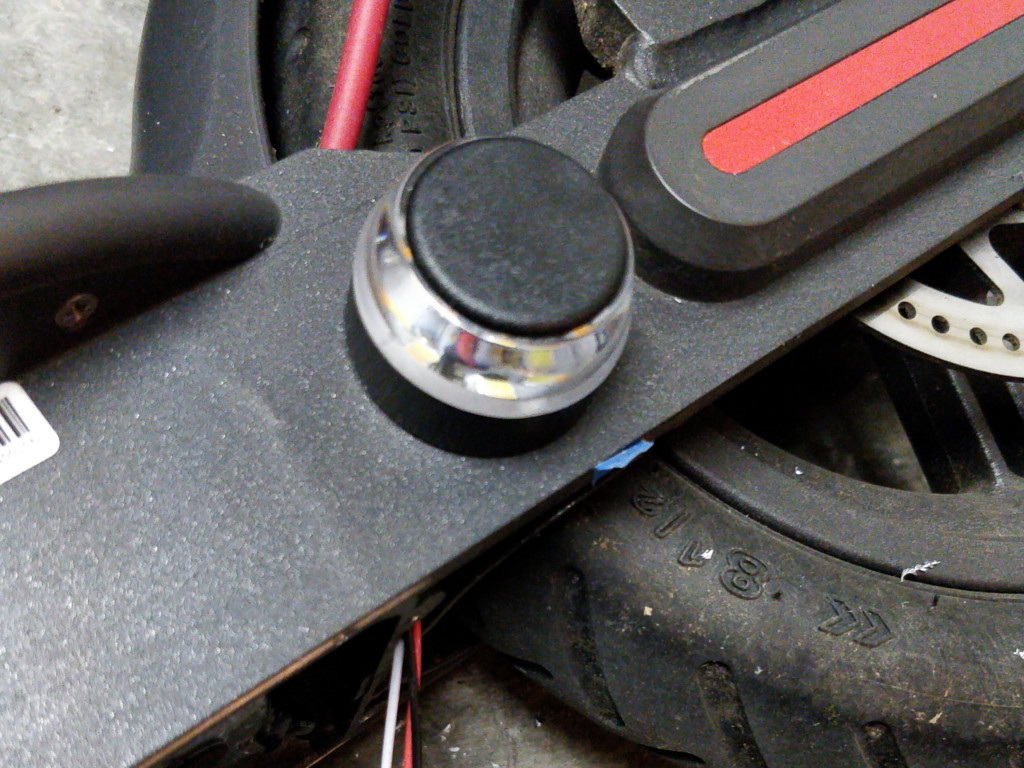
Installing the lights
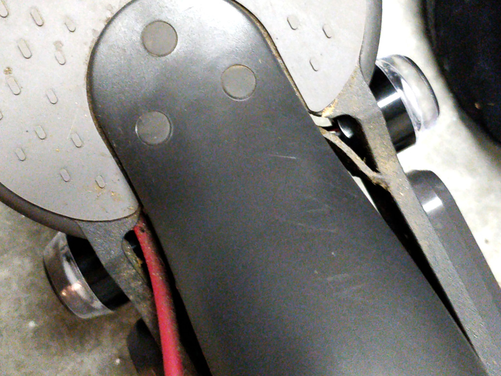
After debating for several weeks, I decided to start with a left and right blinker located towards the back just short of the wheel nut covers. The location is integrated, secure, and easy to run wires.
I wanted to install a second set on the ends of the handlebars, but internal design of them made centering and securing the lights challenging.
That leaves a spot in the front of the footboard as the next most logical and integrated place. However, if placing it as far forward as possible, that aligns the light's nut against the driver board where there is no space for the wiring that has to come out the end of it. I plan to revisit this in the future.
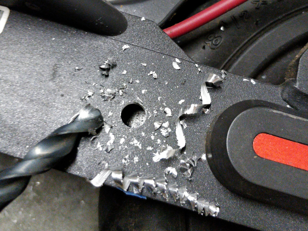
The holes are easy to drill and require cutting the light hollow bolts with hacksaw to allow them to fit. I used a simple foam O-ring as a separator and sealer. The other side of the bolt is not inside the footboard, so they don't have to seal out water, but I just wanted to test them out as the other set of lights would need this.
I ran the wiring through the existing brake light gasket. I cut it slightly from the top, and used electrical tape to seal it as best possible. There's probably a better way, but this works for now!
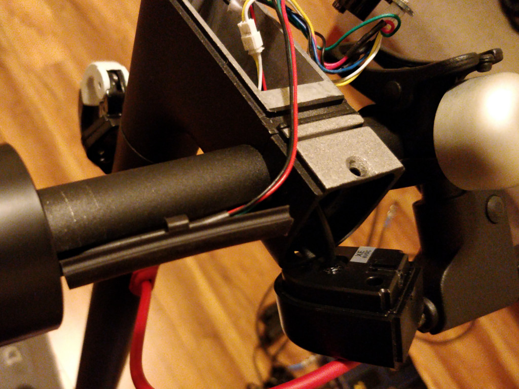
Connecting the handlebar buttons
The final part was connecting the handlebar buttons and buzzer to the arduino in the footboard. I decided to use an ethernet cable to run through the stem. That gave me 8 wires that were all color coded:
- Brown - Ground
- Brown striped - Speaker
- Green - Left button
- Green striped - Right button
- Orange - Left button LED
- Orange striped - Right button LED
- Blue - Horn
- Blue striped - Available
The handlebars disassembled really well. Xiaomi designed them with finesse.
The plate that has the power button on it is just glued in place. I carefully pried it up, and then all remaining screws were pretty obvious.
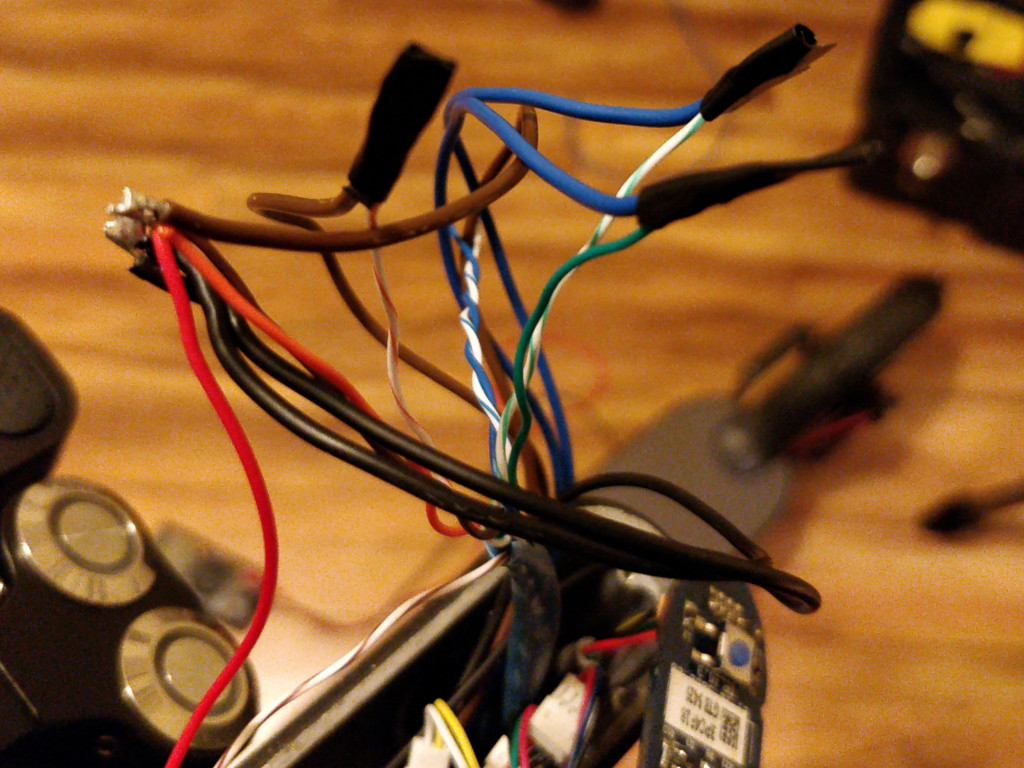
Just a matter of soldering according to the key, routing the button wiring into the space behind the headlight, and smushing the excess wiring and buzzer into the space directly under the power button.

I cut most of the casing off of the two heavy gauge button cables so that they would fit in the gap running into the bluetooth module, and lightly wrapped the exposed wires with electrical tape. Don't mind the rubber bands in the photo.
Working demo
And here's the somewhat finished product, tested for a couple of weeks now. Next up is adding a horn and learning more about how MOSFETs work so that I can also use the white LEDs in the signal lights.
Photos
Not all photos are in this post. See all of them here: Photos of each step of the way
Follow-up work
Nov 25: Added a 5A fuse between the battery splice and the DC DC converter. Surely don't want to have to take apart the BMS to replace a fuse should a short occur.
Nov 25: Fed the scooter's 5V into Arduino pin 2, one of the hardware interrupt pins. Working on putting the Arduino to sleep when the pin reads LOW, and waking it up again via the interrupt. That way, it switches with the scooter.
Dec 7: Rethinking a few things. Having an issue with the scooter's controls causing the arduino inputs to go LOW. I believe it is electrical noise, going to install some stronger pullup resistors. Inspired to use a FET or relay to toggle the whole mod with the scooter's 5V. And testing out microswitches on the grip.
Dec 23: Learning a lot and feeling kind of dumb with my initial hackery, but hey, it's all part of the fun! Tore everything out and improving the design. Not sure why I didn't realize there are smaller boards earlier, but with so tight of a space, it makes zero sense to cram a full-size UNO in. Experimenting with the Particle Photon and the Arduino Nano to fit everything onto a long skinny piece of plastic that goes into the stem connector.
Didn't make sense to try to put the Arduino to sleep. Either switching whole thing with an N-FET gated by the scooter's 5V, or running the Arduino/future Photon directly off of it.
Also, trying 2K pullup resistors for the handlebar switches to correct the Dec 7 issue. And finally, committing to the other set of blinkers on the edges of the handlebar grips, plus the microswitches mounted on them. Planning on posting a follow-up with the improved design.
The .ino is a WIP, also --
blinkers_in_handlebars