Xiaomi M365 Full Mod V3
After lots of trying, failing, and learning, here's a 2021 up-to-date brain-dump about the full M365 package. This is everything I'd do to a stock M365 before using it as a daily driver.
As I write this out, I glance over to the Ninebot MAX G30 I just removed from the box. Twice the range! 10" tubeless pneumatic tires built in! A more integrated bell, a screen, a taller stem...my cursory inspection has me really stoked for the next chapter of scooter modding. It really feels like a supercharged M365.
Given that, this is something of a 2018-2020 retrospective, the beginning of my infatuation with electric scooters. I will still ride my M365, but I'll likely start posting about the G30 now. For now, here are the big points:
Lighting mods to 'speak car' consisting of turn signals, horn, and upgraded headlight. All operated by buttons on the grips.
Firmware enhancements for smooth acceleration/braking, huge improvement from the feel of the controls at stock.
Hardware reinforcements including stem lock, steel battery cover, and rear fender bracket.
Durable and consistent braking via improved brake caliper and larger rotor.
Cosmetic niceties such as reflective decals and a custom color LCD screen showing your current speed and various metrics.
Grip Turn Signals
To start off, the grip lights from my initial turn signal post turned out to be the best ones. I cycled through a couple other models but found they were highest quality, mainly attributed to their aluminum body.
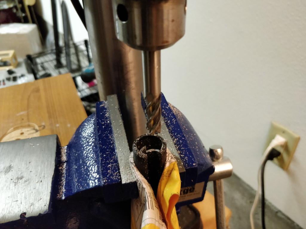
With that in mind, I wanted to do better than loosely attaching it to the edges of the stock rubber grips. The handle bar has a curved inner piece in the way of actually sliding these lights in as they were designed. What I ended up doing is buying some CNC bits and milling out about 1.5" or 38mm of this curved inner piece.
 |
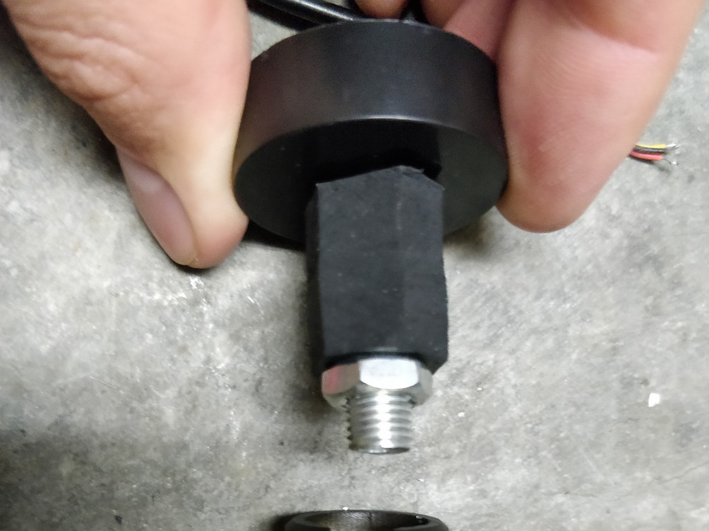 |
Now that the bar ends have room to accommodate the rubber sleeve, another caveat. This sleeve fits a 22mm diameter bike/motorcycle bar, whereas the inner part of the M365 handlebar is slightly smaller. I took out the sleeve, slid it into a bolt, and drilled it loosely into some wood. Then, I sliced into the rubber while rotating it around, shrinking its diameter.
Lastly, the LEDs included in this turn signal are crap. Too dim, wrong color, and in fact defective. Mine only lasted a few months before dying alltogether, so I found some great replacements:
- 20mm star heatsink LEDs (Yellow color is perfect amber color)
- 3W resistors, size is 36R (ohm)
The grip blinkers ended up being useful only for their housing, which turned out fine! I desoldered the stock LEDs and put these star ones in, secured by hot glue, and used a 36 ohm resistor to land at a reasonable brightness/current draw (something like 300 mA @ 12 volts).
Rear Turn Signals
My first idea for rear signals was the same handlebar turn signal models mounted just short of the rear wheel axis. I don't think that mounting provided enough visibility.
To account for all angles, my thinking is that each side needs two blinkers, so four total. For attempt #2 here, I decided to try directly rear-firing signals.
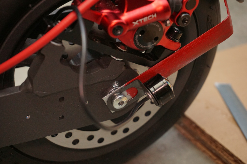
After exploring some options, I settled on some small running lights, in "Yellow" color, that happened to have the perfect bracket for mounting inline with the rear wheel axis bolts. They go great tucked right in with the washer and fender bracket stack, see below.
 |
 |
To pull this off I needed a few holes and cuts. They're a little tricky but this is what I found to work.
First off, with both the depth of the bracket holding these mini lights and the fender bracket, the plastic axis bolt covers need a notch. I marked the edges of the metal, clamped the plastic piece in a vice, and carefully sawed several cuts into it with a hacksaw. Then, a chisel or pliers would work to twist out the chunks.
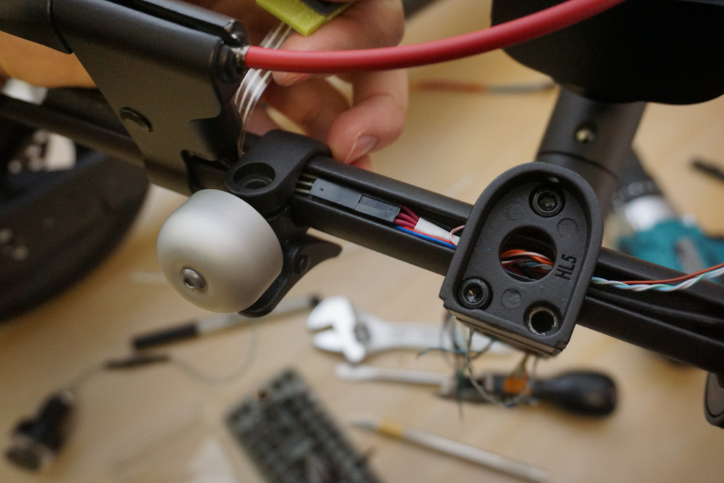
For the wiring, the idea is to route it through two pieces of the aluminum frame, and into the existing hole for the brake light cable. To remain watertight, I carefully cut into the rubber gasket with an xacto blade to accommodate the extra wiring. Once it's all installed, I also applied a bunch of hot glue around the wiring to really make sure it was as sealed as possible.
To route each wire, I eyeballed to match the drillbit diameter with the wire gauge and drilled two holes per side. The first was directly behind the plastic axis bolt cover, the one notched out above. There are already two threaded holes and two nonthreaded holes, so this would be adding fifth hole, nonthreaded. Sure, you could repurpose an existing nonthreaded hole, but they are used for aligning the plastic cover, and I didn't want to throw that off.
So the first hole ended up somewhat towards the back of the area covered by the plastic cover. The key is to route it within that triangular-shaped cavity, made by the aluminum wall shaped around the wheel.
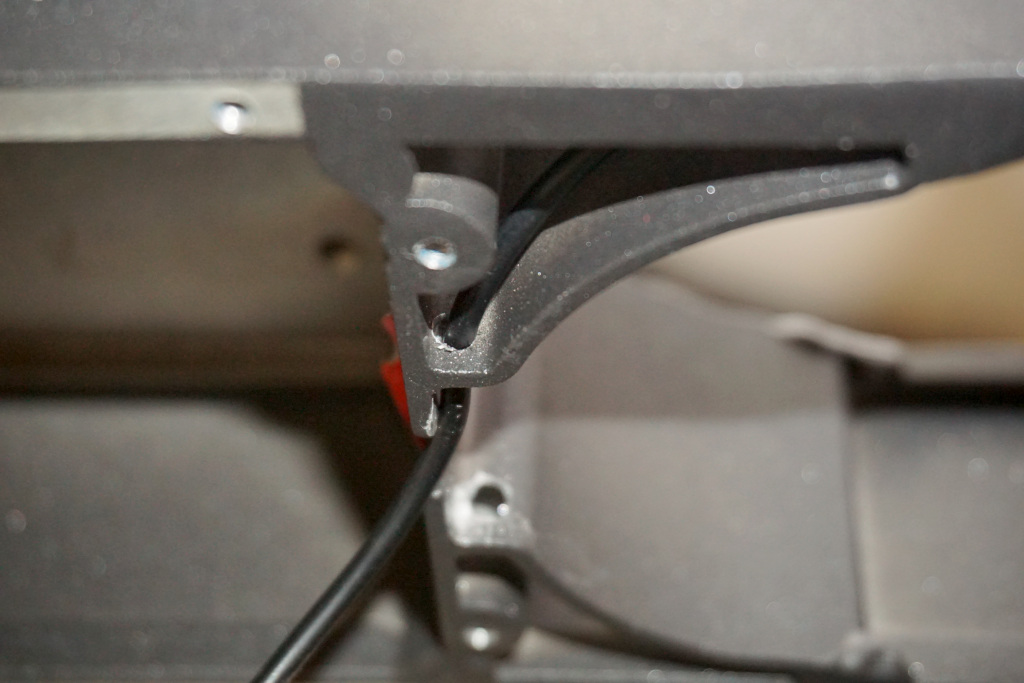
The second hole is immediately next to the stock hole to the footboard. This second hole allows the wires to exit the triangular-shaped cavity— see photo above. This hole requires drilling at a slight angle, otherwise there's no way to get the drill in there. Make sure you leave about 6-8mm of space below the hole to allow the wiring to sit tucked up and away.
Tail Light
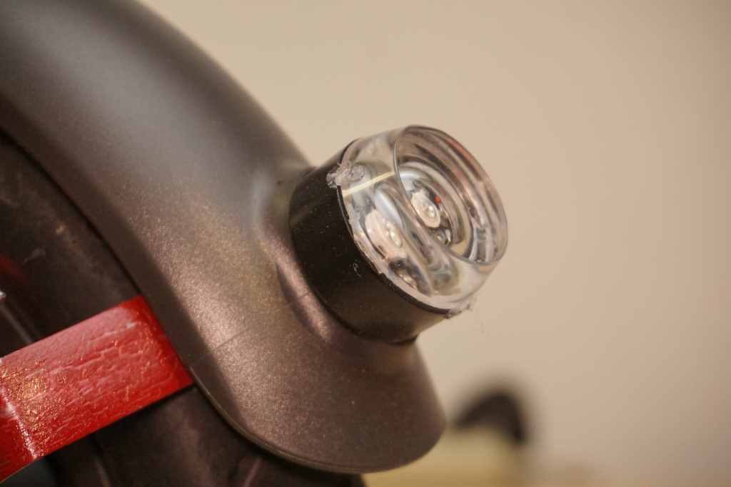
I modded the tail light for version 3. Admittedly the design is scrappy and not the prettiest hack I've built. I took a leftover grip blinker, separated the black plate from it (making it entirely clear plastic), and mounted it using the square hole originally intended for the stock light cable.
The 20mm star heatsink LEDs, in red, turned out great. I used the same resistor as the grip lights to bring it to the right level of current and hot glued it in place.
The win here is better visibility from behind, plus the advantage of blink modes to really make you hard to miss. It's a great safety improvement.
I wired it using the same route as the stock light, though with a thinner wire. Using a 2-pin JST connector, I also recreated the stock connection between the fender and hole into the footboard. This line joins the other two supporting the left and right blinkers. It's quite a bit more to jam in there, but it works just fine with a little x-acto knife work.
UI / Arduino Design
Now, the fun part. How does the rider control everything? Four grip buttons where your index and middle fingers naturally rest. This of course builds on version 2, but the summary is that index fingers control the blinkers while middle fingers control the horn. And an index finger press + hold cycles other functionality.

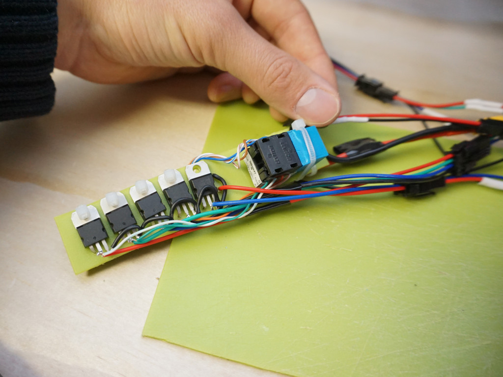
As far as the electronics in the footboard, it's an Arduino Nano, buck converter, and six N-MOSFETs, all arranged in this tight package (photo above). This module does nothing terribly fancy, really it just delegates the 4-button interface to the high-power lights and horn in special ways. See the code, especially the in & out pins, for some more context here.
Try to get everything onto a single piece of plastic that you can slide into that hollow cavity connecting the stem to the footboard. I'm pretty happy with the design of the FETs and ethernet plug on one side, and the two boards laid out side by side on the other.
I like this buck converter coupled with this pinless Arduino Nano. This allows you to solder components such as MOSFETs directly to the Nano, which I ended up doing for compactness. Although I installed 5 MOSFETs, 3 of them can be spaced efficiently via bending the G (gate) pin at a right angle and directly soldering in pins 2, 7, and 12. The remaining 2 MOSFETs would need to be manually connected.
You have less space than you think. Wiring takes up so much space, and it all has to fit in the top area of the footboard, above the DRV. You'll also be so thankful for easily disconnectable wires when trying to tuck it all in. I can't recommend buying an assortment of JST Pigtails enough. Get a bundle of 2, 3, and 4-pin, in 10cm lengths.
When it comes to the wiring between the head unit and footboard, I chose an ethernet cable. I kept the footboard side of the connection a plug, to go into the module. This allows for an easy, organized connection between top and bottom, and uses your limited space well.
 |
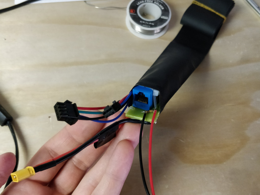 |
The reason an ethernet cable ended up being perfect is because it has 8 strands in just the right gauge. And it turns out you'd need exactly 8 wires at minimum to accommodate the handle functionality:
- Button 1, left index
- Button 2, left middle
- Button 3, right index
- Button 4, right middle
- Ground
- Left turn signal ground
- Right turn signal ground
- 12V right out of buck converter
The first 5 strands support the four buttons: an input line for each, held HIGH via the built in pullup resistors (INPUT_PULLUP), and one ground line which is connected by pressing any button. That in turn pulls each input pin LOW, and the firmware considers the button pressed.
The other 3 strands support the LEDs— left and right negative lines and a shared 12V line. With 36 ohm 3 watt resistors on each, I found that the LEDs together pulled around 300 mA, and I don't think you want to run more than 500 mA through ethernet cabling. Since this high-current lighting is gated by N-MOSFETs, they are differentiated on the negative side. That's why there is a single 12V hot side.
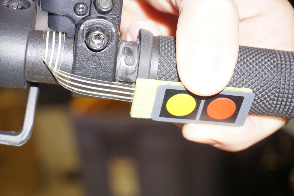
Grips & Buttons
With the addition of end-tip lighting, you either slice off the ends of the stock grips, or find whole new grips. I went with a common model with aluminum rings which you can tighten to keep the grip in place.
I think 2-key Membrane Switches mounted underneath turned out great. To make them more integrated with the grips, I trimmed about 3-4mm from the top and bottom edges. Looking underneath, you can see their conduit channels. Really it's just slicing as close as you can comfortably get without damaging them.
They aren't rigid enough to be operable on their own, so I used some scrap plastic to stick them on. Then, I wrapped the whole thing in heat shrink tubing for color. I was concerned initially this would impact their tactility, but in practice it ended up not at all.
 |
 |
To wire them, you have to disassemble the handlebars completely. Dupont-style male and female pins actually worked really nicely as they plug right into these models and fit in the front cavity of the bar. Note that the clear plastic portion of the switch will end up visible, sitting underneath the throttle and showing a bit under the brake lever. I worried about this too at first, but there isn't a particularly easy way to conceal it.
Firmware
After testing over the past couple years, I'd emphasize a few important details when you tune your firmware. It's about a smooth throttle and brake for me, all other parameters are secondary.
- 38 amps for maximum motor torque. This obviously depends on how much wear and tear you want to tolerate on your motor. I've been running this value for about a year and a half without issue.
- Direct power control ("Russian Algorithm") with a quadratic curve for throttle. To me this is the most natural way for me to control acceleration.
- 2 - 30 amps starting at 86% (or 112 raw value where max is 130) of brake pull range. This softens and backs off braking, allowing your hardware brake to activate first. I prefer that for smoothness and reduced motor wear.
Happy Riding
Thanks for reading my update. I know it's been awhile since I've made time to write a post, but 2020 sucked as we all know and I hope to do more in 2021. I can't wait to see how the G30 turns out with the full treatment!