Minimal parts list to add 12V components to the Xiaomi M365

This list of parts covers a minimum setup you'll need to add 12-volt components to your M365. Once installed, this gets you a 5A / 12V source that switches with the scooter. This also assumes you have some basic tools available such as a soldering iron and electrical tape.
- DC DC Buck Converter, 12V
- XT30 16AWG Pigtails, 2 pairs (2x male, 2x female)
- 5A Automotive Fuse
- Jumper Cable, if you don't have any scrap wiring available
- STP55NF06 MOSFETs 10 piece lot (have to buy a set even though you just need one)
- Resistor, .25W / 100K (have to buy a set even though you just need one)
You'll make a Y-cable with the XT30 pigtails: 1 male to 2 female. One female end goes into your DRV, the other into the last pigtail, a male, which then plugs into your DC DC converter. Its negative lead is gated via the MOSFET.
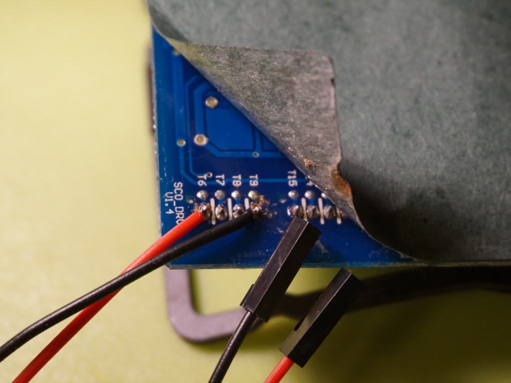
The 5V comes from the 4-pin header in the corner of the ESC. Take some super thin gauge wire and solder it against each pin, under the board. You can use Dupont cable so it's disconnectable, but I like these 2-pin JST pigtails best now.
Why do I need the extra parts and the scooter's 5V?
The 5V from the scooter will drop to 0 when it's off, so gating a MOSFET with it toggles your 12V mods and the stepdown converter with the scooter.
If you do not do that, you will continuously draw current from the battery while turned off. While small, it's significant. I observed my battery percentage slightly dropping overnight before I gated everything.
To tap into the scooter's 5V, I just soldered into the pins on the ESC. See my first turn signal article for more details.
Headlights
Just found some nice options and wanted to curate them here.
- Headlight, 10W Silver Heatsink
- Headlight, 15W Drop Shape
- Headlight, 15W Tubular Shape
- Headlight, 10W with housing