How to install a clone Alibaba front suspension on the M365
 |
 |
There are two popular designs of mechanisms that bring shock absorption to the M365, one by Monorim and a cheaper Chinese knockoff. Both attach to the front steering column and help smooth out your ride pretty well, though at the cost of significant extra weight. I'll admit I tested a suspension for several months before deciding it was too heavy. I'd rather have a lighter, more carry-able scooter than shock absorption. But it was a close decision.
I have also noticed the extra weight shifts the balance when using the kick stand such that it falls over more easily. It still remains upright just fine, but still a drawback.
The Chinese knockoff is riddled with annoying but addressable flaws. If you have a choice, spend $20 more and get the Monorim design. It's the right thing to do as they made the big R&D effort to develop the whole idea. If you already have the Chinese one, however, it's actually a fine part. It just requires a bit of extra tweaking to get right.
So rather than throwing the whole thing out, instead throw out the instruction video or whatever the seller provides. In my opinion the big shortcoming of the clone design is a lack of good installation instructions. I've gone through the trial and error for you and here's what I believe to be the missing manual.
Disassemble the front fork
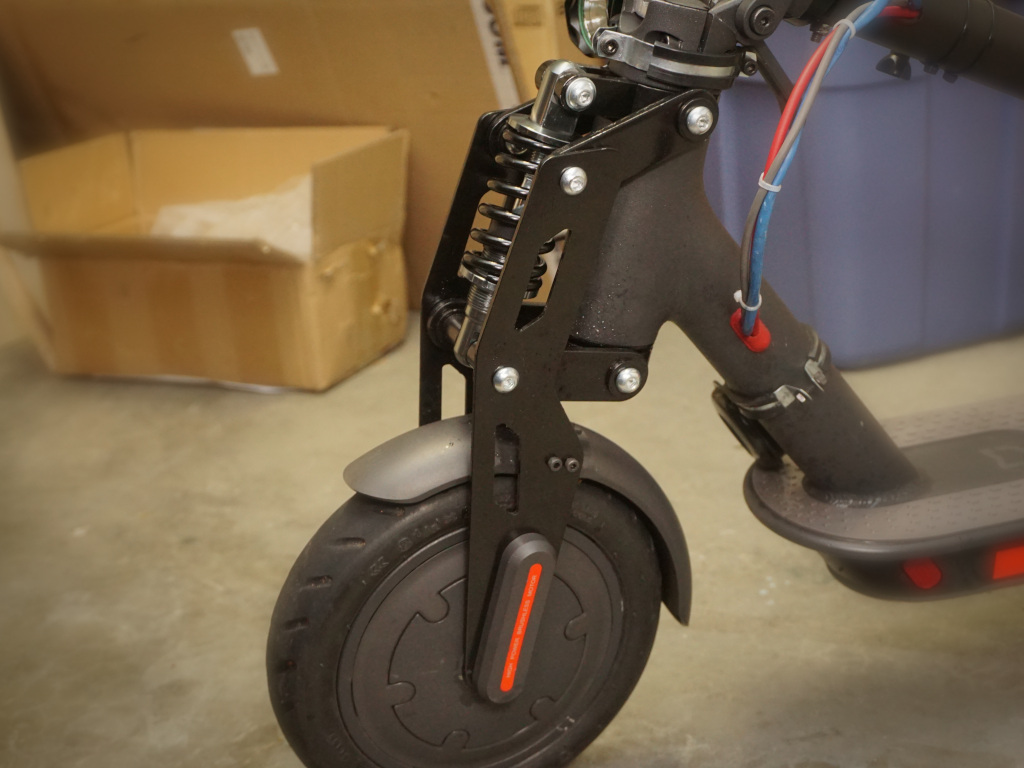
The first step is to disassemble the steering column in order to remove the fork, which this suspension kit replaces. I suggest doing this while placing the bottom of the footboard on the corner of a table with the front wheel hanging off.
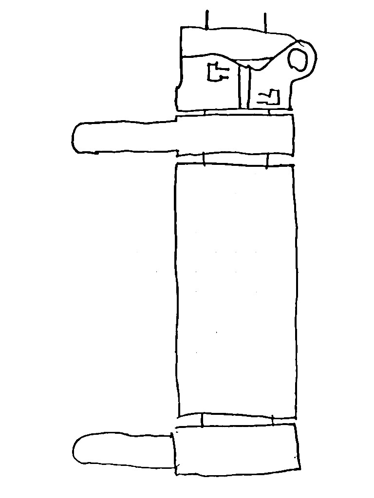
With the stem folded, observe 3 bolts. Loosen the bottom two bolts (2 & 3), but fully unscrew the top bolt (1).

Gently turn the whole stem from left to right, pulling upward to disconnect the part holding the bolts you loosened.
Take off the front wheel. This part is well-covered elsewhere, so I'm going to summarize it as removing the stickers, unscrewing the covers and all bolts underneath, and unscrewing the axis bolts. You can place the wheel on the footboard for now.
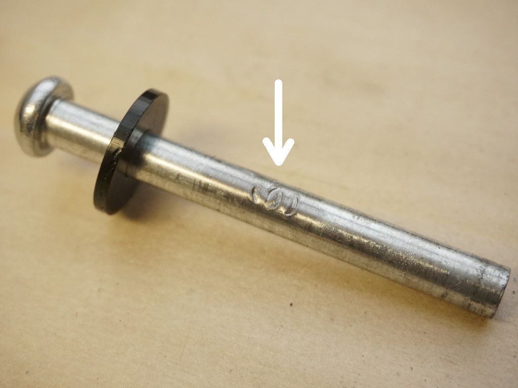
At the top of the fork post, you'll now see a small socket cap bolt going in sideways. This slides into a cavity in the bottom piece of the folding mechanism and makes sure the wheel would never slip loose and turn itself away from where you're steering. Remove this bolt, and slide off the plastic cover and metal bracket below it.
The whole fork is now free. Carefully slide it out the bottom.
Prepare suspension assembly
Unbolt and pull out the top crossbar and the top shock attachment, freeing this top bracket:
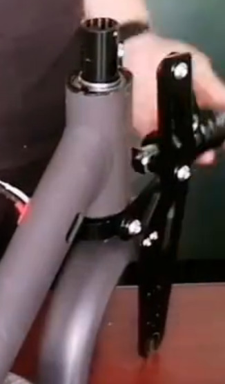
Slide the post up through the bottom, such that the mechanism is in place as shown in this frame of one of the install videos. Don't bother with the fender just yet.
Take note of several parts here:
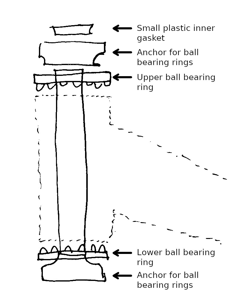
Each ball bearing ring has a flat side, which must face outward. The bearing side goes inward. Those larger curved metal rings hold the flat side in place. To prevent any play in the whole thing, there is also a small plastic inner gasket that goes in the top part of this assembly.
Place the top bracket from step #1 of this section on top of that. Put the small socket cap bolt back in as well, the one mentioned previously that goes in sideways as a safety feature.
Finally, attach the base of the folding mechanism to the top of all of that. Now, there is a very important catch here. The stock top steering bolt (bolt #1 from the initial disassembly instructions) is too long for this assembly. It will damage the upper long pin should you put it in and tighten it. If you damage the pin, it will get stuck when pulled out.
You'll need to find an extra M6 bolt that is shorter. I had this extra one lying around (silver one in picture) that turned out to work fine.
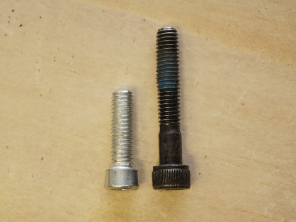
Drop the shorter bolt in the metal adapter thing, and tighten it up. This should tighten the whole post and press the ball bearings into their tracks.
No notch for the oval bracket
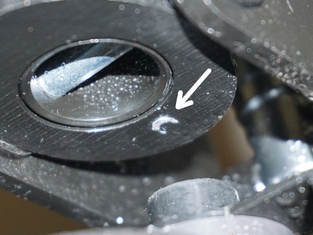
Now that you are just about done assembling the steering post, a big point of confusion with these suspensions is if you need to cut ridges into the sides of the post to slide the oval bracket on. I've noticed some sellers encourage it as an afterthought in their online product details. The one I purchased vaguely hinted at it in one of the photos of the product as a picture of text. I'm not sure they even fully understand the design.
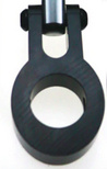
My answer is that you do not need to do this. Before installing this suspension, the oval bracket sets the maximum point of steering left/right. Notice how it works with a small notch sticking upward from the steering housing. The aftermarket suspension actually has a steering track intended to replicate this functionality— look underneath the top bracket (pictured at step #1 above).
So, the final 'stack' of parts should look like this:
Insert top pin, avoid damage from washers
You are now ready to install the longer of the two pins you took out. This one goes through the stem. As you insert, take care to insert the black washers between the scooter and the suspension arms. However, the unit has a design flaw. The inner washers can come into contact with scooter's frame and cause abrasion.
The issue is easily fixed by swapping the inner washers out for smaller rubber gaskets. I found some that fit well in a Harbor Freight hose seal ring assortment.
 |
 |
After several trips of testing, they appeared to clear the frame and I did not notice any more rubbing. I also determined the problem only pertained to the washers connecting to the upper pivot point. However, the lower one may need the same treatment for you— test it out and monitor for any abrasion.
Reinstall wheel and fender
Put the wheel into the new fork of the suspension mechanism and check that the notches on the stock washers on the wheel's axis face downwards.
Now, attach the fender to the new assembly (see photo below for orientation) using the aftermarket shorter bolt, nut, and small screw. The nut goes up top, and you'll drill the small screw into the fender's plastic to avoid any left-to-right play.
Put the fender in place and reinsert the four socket cap bolts that hold it.
 |
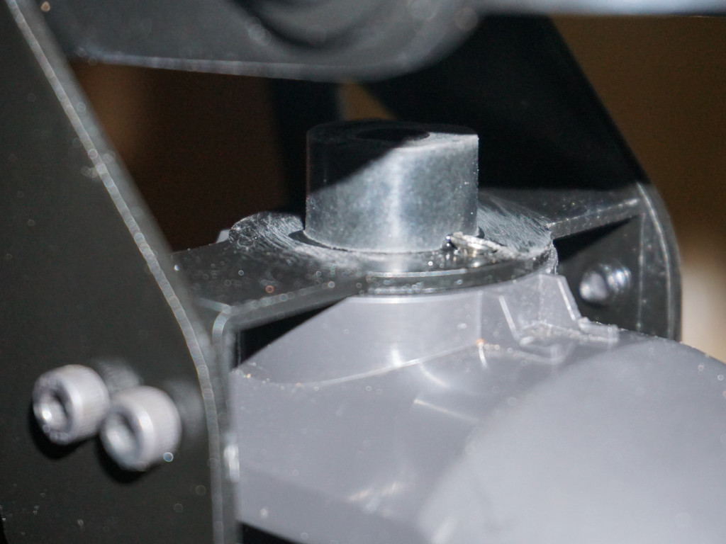 |
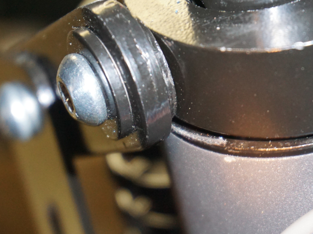
Unfortunately, we have another design flaw. If you hit a really hard bump, this nut can contact the lower circular bracket (see photo). I placed a segment of tubular rubber around the nut which has worked great so far. This is hardly the only way to protect it— I suggest getting creative with what you have available.
Fix holes & install bolt covers
Note there are two lengths of screws that fastened the plastic axis bolt covers to the stock fork. I believe these are M3 or so. You'll want to use the shorter ones to install the covers on the new fork or else they could contact the spinning wheel on the other side.
The final little mistake in the suspension's design is that the protrudy notch things on one of the axis bolt covers don't actually line up with the holes intended to position it properly on the new fork. On mine it was only a problem for the cover on the wire side, the one with the U-shaped reflective sticker.
 |
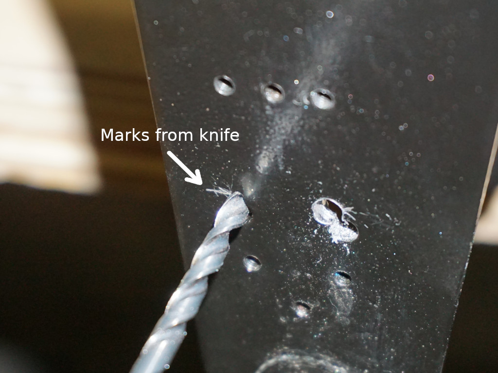 |
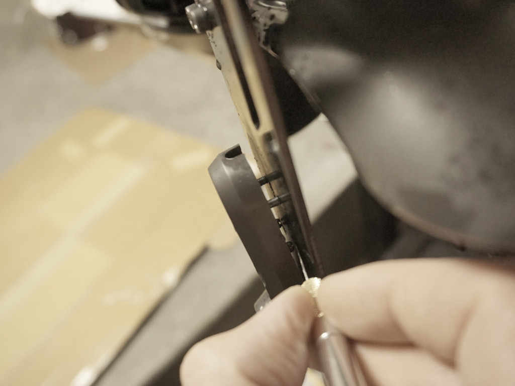
All you need to do is mark or eyeball the correct locations and redrill them. I sort of screwed the part in loosely and wedged an xacto knife in sideways to 'point' at the edge of where the holes needed to be.
Calibrate spring
You're almost done. The final part of this is to calibrate how much absorption is right for you.
With the spring part popped outward as in the photo below, loosen it by grabbing the whole thing and unscrewing (counter clockwise). Shift the parts holding the spring in place down to reveal the nut at the top.
Using wrenches, unscrew that nut and the top connection piece it was securing:
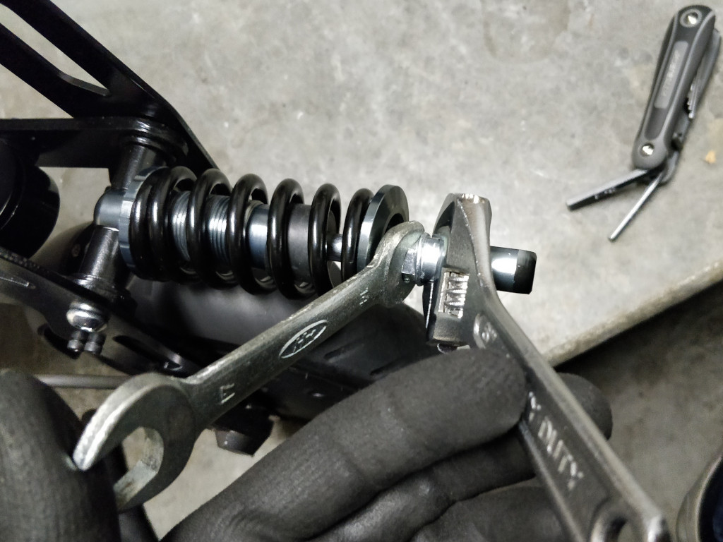

This adjustment is the key to making the unit work properly because the length of the shock dictates how much travel the whole mechanism has, and this is far too short from from the factory. In other words, without adjustment you have very little potential for shock absorption.
I went pretty much as far as it could go while still inserted by about 4 threads, which turned out to provide about 2-3cm more overall length. Tighten the nut back up which should secure the upper connection piece in its new location.
Tighten the bottom ring back up to compress the spring. At this point kinda take a guess at how stiff you'll want it.
Reconnect the top of the shock piece back up. Ride over some bumps and evaluate how smooth the ride is.
Repeat this process until you have found a good tension. It took me about 5 cycles of this to find a comfortable setting.
Once calibrated, I think you'll agree this mod is a bit of a game changer. I've been riding with the suspension for awhile now, and it certainly decreases how much hesitation I have for choppy roads that previously required bracing and slowing down.